Inner components
1
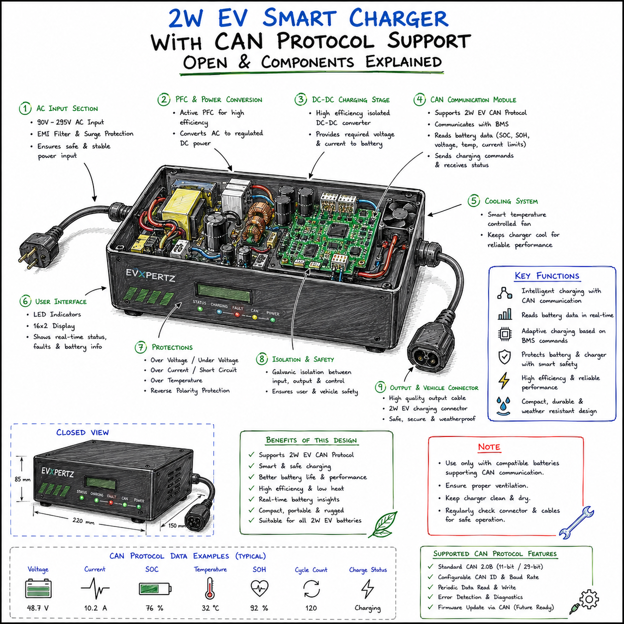
AC input stage
2
EMI filter
3
Surge protection
4
Rectifier
5
PFC stage
6
DC-link capacitors
7
High-frequency transformer
8
DC-DC conversion stage
9
Charging control board
10
Microcontroller / DSP
11
CAN communication interface
12
Current sensing circuit
13
Voltage sensing circuit
14
Temperature sensors
15
Cooling fan / heat sink
16
Isolation and protection circuit
17
DC output connector
18
Status indicators / display
Diagnostic tips
1
Verify charger output voltage and current before connecting to the battery.
2
Confirm CAN compatibility with the vehicle BMS before enabling CAN charging.
3
Verify CAN baud rate and CAN message configuration.
4
Monitor battery SOC, temperature and charging limits through CAN.
5
Check charger cooling and ventilation.
6
Inspect AC input and DC output connectors for heating or damage.
7
Use appropriate over-voltage, over-current and short-circuit protection.